Home > Products - Servo Motors/Drivers/Controllers > Driver TAD8810
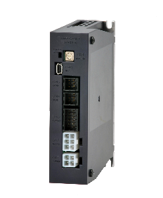
TAD8810 | Drivers
DC Power Type
- Applicable motors :
TBL-iIV Series(Small Size), TBL-iⅡ Series(Small Size), TBL-V Series and TBL-i mini Series - Applicable sensors :
Incremental encoder, serial encoder(17 to 23 bit) and brushless resolver - Features of TAD88 Series
Model designation
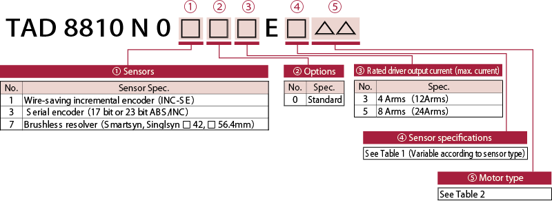
Sensor specifications Table1
| Sensor specifications | |||
|---|---|---|---|
| N01□□ | N03□□ | N07□□ | |
| E1△△ | 2000 C/T | 17 bit-Absolute encoder | 1X-Brushless resolver |
| E2△△ | 2048 C/T | 17 bit-Incremental encoder | 2X-Brushless resolver |
| E3△△ | 2500 C/T | - | (4X-Brushless resolver) |
| E4△△ | - | - | - |
| E5△△ | - | 23 bit-Absolute encoder | - |
| E6△△ | - | 23bit-Incremental encoder | - |
・Those in ( ) refer to products that we will develop and launch in the near future.
Motor and driver applicability Table2
TBL-i mini Series(DC24 V)
| Flange size | Output | Motor model | Applicable driver | Applicable sensor |
|---|---|---|---|---|
| □22 mm | 13 W | TS4631N□□□□E510 | TAD8810N0□□3E□21 | Wire-saving incremental encoder |
| 26 W | TS4632N□□□□E510 | TAD8810N0□□3E□22 | ||
| 40 W | TS4633N□□□□E510 | TAD8810N0□□3E□23 |
TBL-i mini Series(DC48 V)
| Flange size | Output | Motor model | Applicable driver | Applicable sensor |
|---|---|---|---|---|
| □22 mm | 13 W | TS4631N□□□□E600 | TAD8810N0□□3E□61 | Wire-saving incremental encoder |
| 26 W | TS4632N□□□□E600 | TAD8810N0□□3E□62 | ||
| 40 W | TS4633N□□□□E600 | TAD8810N0□□3E□63 |
TBL-V Series(DC24 V/48V)
| Flange size | Output | Motor model | Applicable driver | Applicable sensor | |
|---|---|---|---|---|---|
| DC24 V | DC48 V | ||||
| □20 mm | 5 W | 5 W | TS4734N□□□□E□□□ | TAD8810N07□3E115 | Resolver (Smartsyn:1X-BRX) |
| 10 W | 10 W | TS4735N□□□□E□□□ | TAD8810N07□3E116 | ||
| □28 mm | 20 W | 20 W | TS4737N□□□□E□□□ | TAD8810N07□3E117 | |
| 30 W | 30 W | TS4738N□□□□E□□□ | TAD8810N07□3E118 | ||
| □42 mm | 50 W | 50 W | TS4742N30□□E□□□ | TAD8810N07□5E111 | |
| □56.4 mm | 98 W | 100 W | TS4746N33□□E□□□ | TAD8810N07□5E112 | |
| 92 W | 200 W | TS4747N33□□E□□□ | TAD8810N07□5E113 | ||
| □42 mm | 50 W | 50 W | TS4742N□□□□E□□□ | TAD8810N07□5E211 | Resolver (Singlsyn:2X-BRX) |
| □56.4 mm | 98 W | 100 W | TS4746N□□□□E□□□ | TAD8810N07□5E212 | |
| 92 W | 200 W | TS4747N□□□□E□□□ | TAD8810N07□5E213 | ||
TBL-iⅣ Series(DC24 V)
| Flange size | Output | Motor model | Applicable driver | Applicable sensor |
|---|---|---|---|---|
| □40 mm | 30 W | TSM3101N□□□□E020 | TAD8810N0□03E□44 | All sensors |
| 50 W | TSM3102N□□□□E020 | TAD8810N0□05E□45 | ||
| 100 W | TSM3104N□□□□E020 | TAD8810N0□05E□46 | ||
| □60 mm | 100 W | TSM3201N□□□□E020※ | TAD8810N0□05E□47 |
TBL-iⅣ Series(DC48 V)
| Flange size | Output | Motor model | Applicable driver | Applicable sensor |
|---|---|---|---|---|
| □40 mm | 30 W | TSM3101N□□□□E040 | TAD8810N0□03E□84 | All sensors |
| 50 W | TSM3102N□□□□E040 | TAD8810N0□03E□85 | ||
| 100 W | TSM3104N□□□□E040 | TAD8810N0□05E□86 | ||
| □60 mm | 100 W | TSM3201N□□□□E040 | TAD8810N0□05E□87 | |
| 200 W | TSM3202N□□□□E040 | TAD8810N0□05E□88 | ||
| □80 mm | 200 W | TSM3301N□□□□E040※ | TAD8810N0□05E□89 |
Maximum output is limited when the motor having ※ mark is combined with TAD8810.
TBL-iⅡ Series(DC24 V)
| Flange size | Output | Motor model | Applicable driver | Applicable sensor |
|---|---|---|---|---|
| □40 mm | 30 W | TS4601N□□□□E520 | TAD8810N0□□3E□41 | All sensors |
| 50 W | TS4602N□□□□E520 | TAD8810N0□□3E□42 | ||
| 100 W | TS4603N□□□□E520 | TAD8810N0□□5E□43 | ||
| □60 mm | 100 W | TS4606N□□□□E520 | TAD8810N0□□5E□56 | |
| 100 W | TS4607N□□□□E520 | TAD8810N0□□5E□57 |
TBL-iⅡ Series(DC48 V)
| Flange size | Output | Motor model | Applicable driver | Applicable sensor |
|---|---|---|---|---|
| □40 mm | 30 W | TS4601N□□□□E620 | TAD8810N0□□3E□81 | All sensors |
| 50 W | TS4602N□□□□E620 | TAD8810N0□□3E□82 | ||
| 100 W | TS4603N□□□□E620 | TAD8810N0□□3E□83 | ||
| □60 mm | 100 W | TS4606N□□□□E620 | TAD8810N0□□3E□96 | |
| 200 W | TS4607N□□□□E620 | TAD8810N0□□5E□97 |
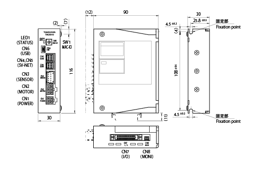
Outline
Specifications
General specifications
| Basic specifications | Power input | Driving power | DC24 V±10 % / DC48 V±10 % |
|---|---|---|---|
| Control power | DC24 V±10 % | ||
| Motor driving system | Transistor PWM system(sine wave drive) | ||
| Structure | Base mounting type(back-to-back mounting only) | ||
| Sensor specifications | N1□□ | Incremental encoder(Wire-saving) | |
| N3□□ | Serial encoder(Smart-ABS/INC) | ||
| N7□□ | Brushless resolver(Smartsyn) 1X, 2X -BRX | ||
| Operating environment conditions | Temperature: 0 to 40 ℃ / Humidity: 90 % RH or lower(no condensation) | ||
| Functions | Communication software specification | SV-NET | |
| Control mode | ①Position control ②Speed control ③Current control(Parameter selection) | ||
| Pulse command input | Pulse mode | ①CCW/CW pulse ②PULSE/Direction(Parameter selection) | |
| Positioning accuracy | Within ±1 pulse(Command standard) | ||
| Analog command input (±10 V) |
Velocity command input Current command input |
Command scale and polarity depend on parameters. 6000 rpm/10 V or maximum current of motor/10 V(Factory setting) |
|
| Command resolution | ±11 bit | ||
| Auto tuning | Executed by switching to supported mode | ||
| Electronic gear | Control the position by multiplying the command pulse by “N” or M” N: Number of command pulse inputted to rotate the motor shaft M times(1 to 230) M: Rotation number of motor shaft per number of command pulse “N”(1 to 214) |
||
| Gain switching function | Switching of control gain is possible via positional error and velocity command value; switching via signal input also possible. |
||
| Recommended load inertia | Within 30 times of motor inertia | ||
| Rotation direction | Both directions possible. CCW rotation is taken as the forward direction of rotation (factory setting). | ||
| Parameters | Parameter setting is possible by connecting to PC(USB, SV-NET) ・Control mode ・Analog command scale ・Position loop gain ・Analog command offset ・Velocity loop gain ・Zero clamp voltage ・Velocity loop integral time ・Acceleration limit ・Feedforward quantity ・Setting for encoder frequency-divided output ・Resonator filter ・Electronic gear ratio ・Velocity limit ・Over-speed alarm level ・Current limit ・Over-load alarm level ・In-position range Among others |
||
| Protection | Hardware error | Over-speed, power device abnormality (over-current), sensor abnormality, driving power abnormality, EEPROM abnormality, CPU abnormality,etc. |
|
| Software error | Over-load, excessive error, etc. | ||
| Alarm history | Capable of memorizing up to 8 alarms | ||
| Display | 2-color LED Control mode, alarm, warning indication |
||
Input/output signals
| I/O | Name | Description(Factory setting) | ||
|---|---|---|---|---|
| Input signals | IN1(SV-ON) | Servo is ON at “1” and OFF at “0”. | 8ch universal input Functions of this can be modified by changing parameters. |
I/F voltage:DC5V 〜 24V “1” L level “0” H level or open |
| IN2(F-LMT) IN3(R-LMT) |
CCW operation is disabled at “0”. Logic alteration is possible. CW operation is disabled at “0”. Logic alteration is possible. |
|||
| IN4(ALM-RST) | Alarm is reset when “1”. | |||
| IN5(C-RST) | Error counter is reset at “1”. | |||
| IN6(EX_ALM) | External alarm when “1” | |||
| IN7(HOME) | Origin signal is ON when “1”. | |||
| IN8(PLS-INH) | Pulse input is ignored when “1”. | |||
| F-PLS R-PLS |
CCW pulse/PULSE input CW pulse/Direction(via parameter) |
f ≦ 500 kHz:Fig.1 f ≦ 200 kHz:Fig.2 |
||
| ANALOG-IN1 | Analog command input(± 10 V) | |||
| ANALOG-IN2 | Analog command input(± 10 V) | Reserve | ||
| 出力信号 | OUT1(ALM) | “0” during alarm and “1” during normal operation |
5ch universal input Functions of this can be modified by changing parameters. |
Open-drain output |
| OUT2(INP) | “1” when position error is set value or below. | |||
| OUT3(RDY) | “1” when servo is ready. | |||
| OUT4(BRK- SG) | “1” when motor stops. | |||
| OUT5(STOP-SG) | “1” when brake is released. | |||
| LEAD LAG |
Outputs frequency-divided sensor signals(. Refer to instruction manual for details) | Line-driver output. | ||
| Z | Outputs Z signal.(Refer to instruction manual for details) | |||
| MONITOR-1 MONITOR-2 |
Monitors ① current command, ② velocity feedback, etc. Parameter-based setting for monitoring content and scale |
|||