Home > Products - Rotary Encoders > Incremental Encoders
Incremental Encoders
A type that outputs a pulse train according to the rotational displacement of the shaft.
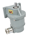
Shaft Type
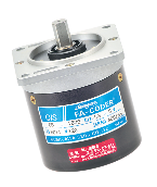
| Model No. | TS53□□N5□□ | TS51□□N□□□ | TS50□□N□□□ | TS50□□N□ | |
|---|---|---|---|---|---|
| Appearance | 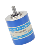 | 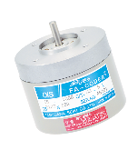 |
 |
 |
|
| Series | OIS38 | OIS66 | OIS68 | OIS128 | |
| Outside Diameter | Φ 38 mm | Φ 66 mm | □ 68 mm | Φ 128 mm,□120 mm | |
| Shaft Diameter | Φ 6 mm | Φ 5 mm | Φ 10 mm | Φ 16 mm | |
| Resolution | 100 to 2,500 C/T | 100 to 5,000 C/T | 25 to 5,000 C/T | ||
| Output Phase | A,B,Z Phase | A,B Phase | |||
| Supply Voltage | DC+5 to +12 V | DC+5,+12 V | DC+24 V | ||
| Consumption Current (NOTE1) |
100 mA Max | 200 mA Max | 300 mA Max | ||
| Output Form | Open Collector Line Driver |
Voltage Open Collector Line Driver |
Voltage Complementaly |
||
| Maximum Response Frequency | 200 kHz | 125 kHz | 25 kHz | ||
| Starting Torque | 4.4×10⁻³ N⋅m Max (45 gf⋅cm Max) |
2.9×10⁻³ N⋅m Max (30 gf⋅cm Max) |
9.8×10⁻² N⋅m Max (1 kgf⋅cm Max) |
2×10⁻¹ N⋅m Max (2 kgf⋅cm Max) |
|
| Moment of Inertia | 1.5×10⁻⁶ kg・m2 Max (15 g⋅cm2 Max) |
3.0×10⁻⁶ kg・m2 Max (30 g⋅cm2 Max) |
3.0×10⁻⁶ kg・m2 Max (30 g⋅cm2 Max) |
5.0×10⁻⁵ kg・m2 Max (500 g⋅cm2 Max) |
|
| Maximun Allowable Rotation (Mechanical Spec.) |
5,000 min-1(rpm) | 7,200 min-1(rpm) | 2,500 min-1(rpm) | ||
| Allowable Shaft Load (NOTE2) |
Radial | 21.6 N Max (2.2 kgf Max) |
98 N Max (10 kgf Max) |
392 N Max (40 kgf Max) |
|
| Axial | 10.8 N Max (1.1 kgf Max) |
12.7 N Max (1.3 kgf Max) |
49 N Max (5 kgf Max) |
||
| Mass (Excluding Cable) |
0.15 kg Max | 0.5 kg Max | 1 kg Max | Mount Type:7 kg Max Flange Type:8 kg Max |
|
| Operating Temp. Range | -10 to +70 °C (Line Dliver type: 0 to +70 ℃) |
0 to +70 ℃ | -10 to +70 °C | -0 to +50 °C | |
| Protective Structure (NOTE3) |
IP50 | IP52 | IP57 | ||
| Vibration (NOTE4) | 49 m/s2 (5 G) | 98 /s2 (10 G) | |||
| Shock (NOTE5) | 490 m/s2 (50 G) | 980 m/s2 (100 G) | |||
- NOTE 1) Consumption Current: Specified value for an output circuit with no load.
- NOTE 2) Specified value for the Allowable Shaft Load. Usage to within 20 % of the specified value is recommended on actual use.
- NOTE 3) Regarding special specifications for the Protective Structure, please consult us.
- NOTE 4) Vibration: Value which satisfies the conditions of 2 hours each for axes X, Y and Z, for a total of 6 hours.
- NOTE 5) Shock: Value which satisfies the conditions of 3 times each for axes X, Y and Z, for a total of 18 times.
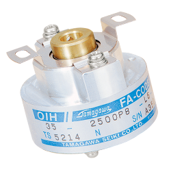
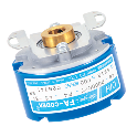
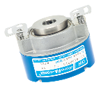
Hollow shaft Type
| Model No. | TS52□□N3□□ | TS52□□N5□□ | TS52□□N4□□ | |
|---|---|---|---|---|
| Appearance | 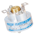 |
 |
 |
|
| Series | OIH35 | OIH48 | OIH60 | |
| Outside Diameter | Φ35 mm | Φ48 mm | Φ60 mm | |
| Moter Shaft Diameter | Φ6 mm | Φ8 mm | Φ20 mm | |
| Resolution | 500 to 6,000 C/T | 1,000 to 12,000 C/T | 1,000 to 8,192 C/T | |
| Output Phase | A,B,Z,U,V,W Phase | |||
| Supply Voltage | DC +5 V | |||
| Consumption Current (NOTE1) |
200 mA Max | |||
| Output Form | Line Driver | |||
| Maximum Response Frequency | 200 kHz | |||
| Starting Torque | 5.9×10⁻³ N⋅m (60 gf⋅cm Max) |
9.8×10⁻³ N⋅m (100 gf⋅cm Max) |
||
| Moment of Inertia | 1.0×10⁻⁶ kg・m2 Max (10 g・cm2 Max) |
6.5×10⁻⁶ kg・m2 Max (65 g・cm2 Max) |
||
| Maximun Allowable Rotation | 6,000 min-1(rpm) | |||
| Allowable Shaft Load (NOTE2) |
Radial | Mounting Tolerance Radial 0.05 mm TIR Max Axial 0.2 mm Max Shaft Inclination 0.1°Max |
||
| Axial | ||||
| Mass (Excluding Cable) |
0.2 kg Max | 0.3 kg Max | 0.5 kg Max | |
| Protective Structure (NOTE3) |
IP40 (Electronic Circuits Disclosed) |
IP40 | ||
| Operating Temp. Range | -20 to +85 °C | |||
| Vibration (NOTE4) | 49 m/s2 (5G) | |||
| Shock (NOTE5) | 490 m/s2 (50 G) | 980 m/s2 (100 G) | ||
- NOTE 1) Consumption Current: Specified value for an output circuit with no load.
- NOTE 2) Specified value for the Allowable Shaft Load. Usage to within 20% of the specified value is recommended on actual use.
- NOTE 3) Regarding special specifications for the Protective Structure, please consult us.
- NOTE 4) Vibration: Value which satisfies the conditions of 2 hours each for axes X, Y and Z, for a total of 6 hours.
- NOTE 5) Shock: Value which satisfies the conditions of 3 times each for axes X, Y and Z, for a total of 18 times.
Magnetic Encoder
| Model No. | TS5291N100 | TS5291N500 |
|---|---|---|
| Appearance | 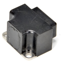 |
 |
| Series | MIB0.4 | |
| Resolution | 1,024 C/T (No. of teeth 128) |
128 C/T |
| Output Phase | A,B,Z Phase | |
| Supply Voltage | DC+5 V | |
| Consumption Current | 200 mA Max | 100 mA Max |
| Output Form | Line Driver | Analog output |
| Maximum Response Frequency | 512 kHz | 128 kHz |
| Maximun Allowable Rotation(Electrical Spec.) | 30,000 min-1(rpm) | 40,000 min-1(rpm) |
| Air gap berween Sensor & Wheel | 0.15±0.01 mm | |
| Radial in alignment between Sensor & Wheel | ±0.3 mm | |
| Axial in alignment between Sensor & Wheel | ±0.5 mm | |
| Mass (Excluding Cable) |
0.5 kg Max | |
| Protective Structure | IP66 | |
| Operating Temp. Range | -20 to +85 °C | |
| Vibration | 80 m/s2 Max 3-way 3 Hr(10 to 2,000 Hz) |
|
| Shock | 1,000 m/s2 11 ms | |
- NOTE 1) Consumption Current: Specified value for an output circuit with no load.
- NOTE 2) Specified value for the Allowable Shaft Load. Usage to within 20% of the specified value is recommended on actual use.
- NOTE 3) Regarding special specifications for the Protective Structure, please consult us.
- NOTE 4) Vibration: Value which satisfies the conditions of 2 hours each for axes X, Y and Z, for a total of 6 hours.
- NOTE 5) Shock: Value which satisfies the conditions of 3 times each for axes X, Y and Z, for a total of 18 times.


